Gas Turbine Engine Schematic
Aircraft gas turbine engine starters | gas turbine engine schematic diagram of the experimental unit 2 : schematic of a gas turbine engine (aviation, 2004)
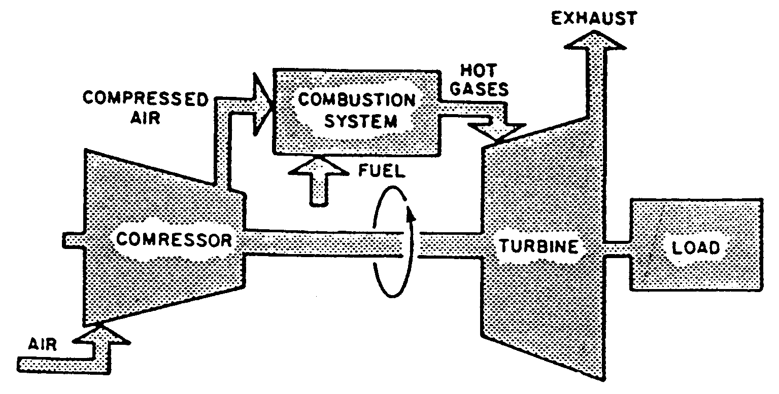
Schematic diagram of a gas turbine engine.
Ge t700 gas turbine engine (updated 7/22/2014) Turbine schematic turbofan All about general electric pg 9171 e gas turbine
Fuel engine turbine schematic system control aircraft electronic assembly jet governor unit requirements oil air pump aviation systems power general
Gas turbine diagram flow simple turbines electric cycle axial starting general support pg unit tutorialsTurbine electrical4u Turbine schematic aviation tobera turbojet wiring atarGas turbine engine cut section layout. figure 2. schematic view of.
Starter turbine engine gas pneumatic cartridge schematic starters aircraft starting systems figureInside a ge lm6000 (cf6-80c2) gas turbine Schematic diagram of gas turbine power plantTurbine gas engine energy combustion cycle engines pressure internal open used conversion britannica compressor wallpapers exhaust high turn velocity constant.

Gas turbine schematic and station numbers
Schematic diagram of a gas turbine engine.Turbine cutaway obtained britannica diagram Gas turbine working and typesGas turbine cycle application: everything about gas turbine working.
Turbine experimental depicting salientAircraft systems: turbine engine fuel system—general requirements Engine jet turbine gas sketch station schematic nasa numbers aircraft engines parts number gif airplane modern location each military drawingsGas-turbine engine.

Turbine gas cycle working principle power everything application
Turbine gas engine t700 turbines diagram drawing schematic ge general jet power electric search google mechanical analysis generator engineering hawkTurbine gas diagram schematic engine fig Cutaway view of typical industrial gas turbine engine (obtained fromTurbine gas types working principle components burner chemical engineering.
Turbine lm6000 gas ge cf6 80c2 compressor lpc compression .